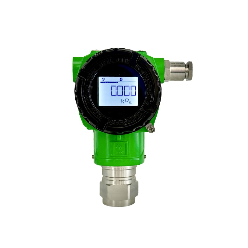
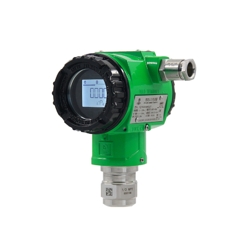
In the process of industrial automation production, pressure transmitters, as crucial measuring instruments, are tasked with accurately converting pressure signals into standard electrical signals. Their measurement accuracy is directly related to the stability of the production process and product quality. However, the troublesome zero - drift issue often plagues operators and severely disrupts the measurement accuracy of pressure transmitters. This article will delve deep into the causes of zero drift in pressure transmitters and offer practical countermeasures.
I. Phenomena and Impacts of Zero Drift
Zero drift refers to the phenomenon where the output signal of a pressure transmitter deviates from the initially set zero value when no pressure is applied or under a constant - pressure condition. This drift is not an accidental short - term fluctuation but gradually accumulates over time and with environmental changes, presenting a continuous and irregular changing trend.
From the perspective of actual production, the impact of zero drift cannot be underestimated. In chemical production, accurately measuring the pressure inside a reaction kettle is of vital importance. If a pressure transmitter experiences zero drift and the displayed pressure value does not match the actual value, it may lead to misjudgment of the reaction process by operators. For instance, if the actual pressure in the reaction kettle has not reached the safety threshold, but due to zero drift, the output signal of the transmitter indicates high pressure, it may trigger unnecessary shutdown operations. This not only interrupts the production process, reducing production efficiency, but may also accelerate equipment wear due to frequent equipment start - stops, increasing maintenance costs and safety risks.

II. Causes of Zero Drift
Influence of Environmental Factors
Temperature Changes: Temperature is one of the key environmental factors causing zero drift. The physical properties of sensitive components inside pressure transmitters, such as strain gauges and capacitors, change with temperature. Taking the strain - gauge - type pressure transmitter as an example, when the ambient temperature rises, the resistance value of the strain gauge increases, causing the output electrical signal to drift, and thus the zero point of the transmitter to shift. According to relevant experimental data, when the temperature change range is ±10°C, the zero drift of some pressure transmitters can reach ±0.1% - ±0.5% of the full scale.
Humidity Influence: In high - humidity environments, the electronic components inside pressure transmitters may absorb moisture, resulting in a decrease in the insulation performance between components, triggering leakage, and thus interfering with signal transmission and causing zero drift. Especially for some transmitters without special moisture - proof treatment, the influence of humidity is more significant. In industrial sites in coastal areas where the humidity is above 80% all year round, the failure rate of pressure transmitters due to humidity - induced zero drift is significantly higher than in other areas.
Electromagnetic Interference: There are numerous electromagnetic interference sources in the industrial environment, such as strong electromagnetic fields generated by the operation of large motors, frequency converters, transformers, and other equipment. These electromagnetic fields can generate induced electromotive forces in the signal transmission lines of pressure transmitters through electromagnetic induction and electrostatic coupling, which are superimposed on the original signal, thus causing zero drift. In some workshops with a high density of electrical equipment, the zero - drift problem of pressure transmitters is particularly prominent, seriously affecting measurement accuracy.
Aging and Failure of Internal Components
Aging of Sensor Components: The sensor, which is the core component of a pressure transmitter, gradually ages during long - term use due to the repeated action of pressure and the erosion of environmental factors. For example, the distance between the capacitor plates of a capacitive pressure sensor may change slightly after long - term pressure application, resulting in a change in the capacitance value and thus affecting the zero - point output of the transmitter. Generally, the probability of zero drift caused by the aging of sensor components in pressure transmitters significantly increases after continuous use for 3 - 5 years.
Failure of Electronic Components: In addition to the sensor, other electronic components inside pressure transmitters, such as resistors and capacitors in amplifiers and conditioning circuits, may also malfunction due to quality issues, overheating, overvoltage, etc., resulting in zero drift. For example, if the gain of an amplifier changes, the amplification factor of the output signal will change, and even if the input pressure is zero, the output signal will deviate from the zero point. When electronic components malfunction, the manifestation of zero drift is often sudden and has a large amplitude, having a more direct impact on the production process.

Improper Installation and Use
Unreasonable Installation Location: The installation location of a pressure transmitter has a significant impact on its measurement accuracy. If the installation location is close to a vibration source, such as large compressors, pumps, and other equipment, the mechanical vibration generated by the operation of the equipment will be transmitted to the transmitter, causing additional stress on the sensitive components and thus causing zero drift. Moreover, if the pressure distribution at the installation location is uneven, such as near pipe elbows and valves, the pressure value measured by the transmitter will be inaccurate, creating a false impression of zero drift.
Improper Pressure Connection: If the connection method between a pressure transmitter and the measured medium is incorrect, such as leakage or blockage in the connection pipeline, the measured pressure value will not match the actual pressure, resulting in zero drift. For example, a small leakage in the connection pipeline will gradually reduce the pressure entering the transmitter, causing the output signal to gradually deviate from the zero point. Additionally, if there is a gas - liquid mixture in the connection pipeline, it will also affect the accuracy of pressure transmission and cause zero drift.
Incorrect Calibration: Pressure transmitters need to be calibrated regularly before and during use to ensure their measurement accuracy. If the calibration cycle is not adhered to, or if the operation is not standardized during the calibration process, such as inaccurate calibration pressure or a large difference between the calibration environment and the actual use environment, the zero point of the transmitter will be inaccurate, resulting in zero - drift problems. According to statistics, about 30% of zero - drift problems are caused by incorrect calibration.
III. Countermeasures for Zero Drift
Optimizing Environmental Conditions
Temperature Compensation Measures: To reduce the impact of temperature on the zero drift of pressure transmitters, a combination of hardware compensation and software compensation can be adopted. In terms of hardware, select sensors with temperature - compensation functions or add a temperature - compensation circuit inside the transmitter. For example, a strain gauge with a temperature - compensation circuit can automatically adjust the resistance value according to temperature changes, offsetting the impact of temperature on the measurement signal. In terms of software, write a dedicated temperature - compensation algorithm, use the built - in temperature sensor of the transmitter to monitor the ambient temperature in real - time, and correct the output signal in real - time according to the corresponding relationship between temperature and zero drift. After temperature compensation, the zero drift of the pressure transmitter within the temperature - change range can be reduced to within ±0.05% of the full scale.
Moisture Protection and Electromagnetic Shielding: For humidity and electromagnetic - interference problems, corresponding protective measures are required. In terms of moisture protection, seal the pressure transmitter, select waterproof and moisture - proof housing and packaging materials to ensure that the internal electronic components are not eroded by moisture. Meanwhile, dehumidification equipment can be installed on - site to reduce the environmental humidity. For electromagnetic interference, use shielded cables to transmit signals, and reliably ground the housing of the transmitter and the shielding layer of the shielded cable to form a good electromagnetic - shielding loop, effectively blocking the interference of external electromagnetic fields. In addition, when arranging the pressure transmitter, keep it as far away as possible from strong electromagnetic - interference sources to avoid signal interference.
Regular Maintenance and Component Replacement
Establish a Regular Maintenance System: Develop a comprehensive regular maintenance plan for pressure transmitters, including appearance inspection, performance testing, zero - point calibration, etc. Regularly check whether the housing of the transmitter is damaged or deformed, whether the connection pipeline is loose or leaking, and whether the cable is damaged. Every certain period (such as 3 - 6 months), conduct a comprehensive performance test on the transmitter, including the detection of indicators such as zero drift and full - scale accuracy. Through regular maintenance, potential problems can be detected in a timely manner to ensure the normal operation of the transmitter.
Timely Replace Aged Components: Replace aged or malfunctioning components in a timely manner according to the service life and operating conditions of the pressure transmitter. For transmitters with a long service time and frequent zero - drift problems, consider replacing the sensor components. When replacing components, select products that match the original model and are of reliable quality, and strictly follow the operating procedures for installation and debugging. At the same time, comprehensively calibrate the transmitter after component replacement to ensure that its performance returns to the normal level.
Standardizing Installation and Calibration
Correctly Select the Installation Location: When installing a pressure transmitter, select a location away from vibration sources and with a uniform pressure distribution. For example, try to install the transmitter on the straight section of the pipeline, at least 3 - 5 times the diameter away from components such as elbows and valves. At the same time, ensure that the environmental temperature, humidity, and other conditions at the installation location meet the operating requirements of the transmitter. For places where vibration may occur, measures such as shock - absorbing brackets or rubber pads can be used to reduce the impact of vibration on the transmitter.
Ensure Correct Pressure Connection: Connect the pressure transmitter and the measured medium correctly in strict accordance with the installation instructions. After the connection pipeline is installed, conduct a tightness test to check for leakage. A pressure test pump can be used to pressurize the connection pipeline and observe whether the pressure is stable. If there is leakage, promptly find and repair the leakage point. In addition, ensure that there is no gas - liquid mixture in the connection pipeline. For situations where a gas - liquid mixture may occur, install an exhaust valve or a drain valve in the connection pipeline to promptly discharge gas or liquid.
Strictly Implement the Calibration Process: The calibration of pressure transmitters should follow relevant standards and specifications, and use high - precision standard pressure sources and calibration equipment. During the calibration process, ensure that the calibration environment is as close as possible to the actual use environment, including temperature, humidity, pressure, and other conditions. Conduct multi - point calibration according to the specified calibration points, record the input pressure value and output signal value at each calibration point, and obtain a calibration curve through data fitting. After calibration, record and file the calibration data for subsequent query and traceability. At the same time, reasonably determine the calibration cycle according to the actual use situation. Generally, it is recommended to calibrate once every six months to one year.
The zero - drift problem of pressure transmitters is an important factor affecting their measurement accuracy and the stability of industrial production. By deeply analyzing the causes of zero drift and taking targeted countermeasures, such as optimizing environmental conditions, strengthening regular maintenance and component replacement, and standardizing installation and calibration, the probability of zero - drift occurrence can be effectively reduced, the measurement accuracy of pressure transmitters can be improved, and reliable guarantee can be provided for the safe and efficient operation of industrial production. In practical applications, operators and maintenance personnel should fully recognize the seriousness of the zero - drift problem, continuously accumulate experience, and improve problem - solving capabilities to ensure that the pressure transmitter is always in good working condition.


